
Birefringent crystals are widely used to fabricate optical passive devices such as optical isolator, optical circulator, polarization beam combiner/splitter, optical interleaver. The mostly used crystals are uniaxial, such as YVO4 and LiNbO3.
Birefringence in Uniaxial Crystal
Wave normal K is the normal of equalphase surface which describes the transmission of wave phase. Ray S is the normal of wave front which describes the transmission of optical energy. When light incidents on the air-crystal (uniaxial) interface, there are usually two refractive rays, o-ray So and e-ray Se. The direction of each ray depends on the direction of corresponding wave normal.
Fig.1 shows the optical waves and rays in a positive uniaxial crystal. In Fig.1(a), the wave normal is parallel to the optical axis, thus no birefringence happens. There is only one wave normal Ko and one ray So. In Fig.1(b), the wave normal is perpendicular to the optical axis, birefringence happens. Wave normal Ko of o-wave, wave-normal Ke of e-wave, o-ray So, and e-ray Se are in the same direction, while the transmission speeds are different. In a positive uniaxial crystal, o-ray is faster, while in a negative uniaxial crystal, e-ray is faster. In Fig.1(c), the wave normal is in an arbitrary direction. The direction of So keeps coincidence with Ko, while Se deviates from Ke. Note that o-wave and e-wave transmit independently, thus the wave normal Ko and Ke are usually in different directions.
The refractive index of o-wave in a uniaxial crystal is no, whatever direction is the wave normal. However, the refractive index of e-wave is given in Eq. (1), depending on the direction of e-wave normal Ke. Note that θ is the angle between wave normal Ke and optical axis.

(1)
The deviation angle α between Se and Ke is given by Eq. (2), also depending on the direction of e-wave normal Ke.

(2)

The refraction of optical rays at the air-crystal interface is summarized in Fig.2. Note that positive uniaxial crystal is selected as the sample. In Fig.2(a), optical wave transmits alone the direction of optical axis, thus no birefringence happens. In Fig.2(b), optical wave incidents on the interface normally and the optical axis is parallel to the interface. Thus Ko, So, Ke and Se are in the same direction, while the transmission speeds are different. Waveplates are designed based on this circumstance. In Fig.2(c), optical wave incidents on the interface normally, while the optical axis is in an arbitrary direction. Birefringence happens. Ko, So and Ke are in the same direction, while Se deviates from them. Beam displacers are designed based on this circumstance. In Fig.2(d), optical wave incidents on the interface obliquely. So keeps coincidence with Ko, while Se deviates from Ke. Note that Ko and Ke deviate too, which is different from the circumstance in Fig.2(c).

When refracted at the air-crystal interface, the direction of wave normal K can be calculated based on Snell’s Law, as Eq. (3). For o-wave, optical ray So coincidences with wave normal Ko. Thus the refractive angle θ2o of Ko and So is obtained simultaneously, given n2=no in Eq. (3).

(3)
However, Se deviates from Ke for e-wave. Moreover, the refractive index of e-wave depends on the direction of Ke in the crystal, as Eq. (1). It usually needs the combination of Eq. (1) and (3) to obtain the refractive angle θ2e of e-wave (for Ke) and the angle θ between Ke and optica l axis. Then the deviation angle α between Se and Ke can be calculated according to Eq. (2) and thus the direction of Se is obtained.
Waveplates
Waveplate is a widely used optical element made of uniaxial crystal. It is a thin plate with optical axis parallel to the surface. The direction of Ko, So, Ke and Se coincides, while the transmission speed is different, as shown in Fig.3. For convenience of application, fast axis F and slow axis S in the cross section are defined. Fast axis means that optical wave with optical vector (i.e. polarization direction) along this axis travels faster, while slow axis means that optical wave with optical vector along this axis travels slower. In a waveplate made of positive uniaxial crystal, fast axis is perpendicular to optical axis. While in a waveplate made of negative uniaxial crystal, fast axis is parallel to optical axis.

For a waveplate with a thickness of d, the phase delay between optical wave polarized along fast axis and that polarized along slow axis is given by Eq. (4).

(4)
When δ=2π, π, π/2, it is called full waveplate (FWP), half waveplate (HWP) and quarter waveplate (QWP), respectively. Waveplates introduce delay between two orthogonally polarized factors of an incident light and thus change its state of polarization (SOP). A FWP doesn’t change the SOP of light. A QWP converts a circularly polarized (CP) light into a linearly polarized (LP) light or vice versa when optical vector of the incident LP light splits the fast and slow axes of the QWP equally. When a LP light passes a HWP, it keeps as a LP light, while the optical vector is rotated. As shown in Fig.4, the optical vector Ein of the incident light is at the right of the fast axis of the HWP with an angle of θ. After passing the HWP, the optical vector Eout of the outgoing light is rotated by 2θ to the left of the fast axis. Eout is the mirrored image of Ein around the fast axis.

Faraday Effect
When a LP light passes some materials (such as quartz, sugar crystal), it keeps as a LP light while the optical vector is rotated. These materials are called optically active materials. Some materials have optical activity intrinsically, while some materials only show optical activity when exerted with magnetic field. The latter is called Faraday effect, as shown in Fig.5.

For a material with intrinsic optical activity, the rotation angle of optical vector is given by Eq. (5), where l is the length of optical active material that light passes and α is the specific rotation. The optical vector may be rotated clockwise or anti-clockwise when the observer is facing the transmitting direction of light. The former is called left-handed optical activity, while the latter is called right-handed.

(5)
For a material which only shows optical activity in magnetic field, the rotation angle of optical vector is given by Eq. (5), where V is Verdet constant of the material, B is the magnetic field intensity and l is the length of material that light passes. When the magnetic field is not uniform, Eq. (6) is modified as Eq. (7). The rotatory angle is obtained through integration.

(6)

(7)

The difference between intrinsic optical activity and Faraday effect is that the former is reciprocal and the latter is nonreciprocal, as shown in Fig.6. In a material with intrinsic optical activity, the rotatory direction of optical vector depends on the transmitting direction of light. When a LP light passes forward or backward, the optical vector is rotated in reverse directions. Thus the orientation of the optical vector keeps unchanged in a unified coordinate system. Fig.6(a) shows the circumstances when a LP light passes a right-handed optical active material. The optical vector recovers to the original orientation after a round pass through the plate. The change of SOP is reciprocal.
However, in a material which only shows optical activity in magnetic field, the rotatory direction of optical vector depends on the direction of magnetic field. Fig. 6(b) the circumstances when a LP light passes an optical active material in magnetic field. The optical vector is rotated in right-handed and left-handed directions when light transmits forward and backward, respectively. Thus the rotatory angle is doubled in a unified coordinate system after a round pass through the plate. The change of SOP is nonreciprocal.
The nonreciprocal change of SOP in Faraday effect is used to fabricate nonreciprocal optical devices such as optical isolators and optical circulator. The material for Faraday rotators (FRs) used in these devices is a Bi-substituted rare-earth iron garnet single crystals (RIG) grown by liquid phase epitaxy. The rotatory angle is maximized to a fixed value when the intensity of magnetic field is saturated. The maximized angle dependents on the thickness of the epitaxial RIG film on the substrate. The most commonly used FR has a rotatory angle of 45º.
Faraday Rotator + Half Waveplate
In optical circulators and some optical isolators, FR+HWP is a commonly used composite structure, as shown in Fig.7. The FR is placed in magnetic field with saturated intensity and the rotatory angle is 45º. The Fast axis of the HWP is in an orientation of 67.5º. When the LP light passes FR+HWP forward or backward, the optical vector is rotated by 90º or keeps unchanged.

Beam Displacer
Beam displace (BD) is a birefringent block used for polarization diversity of the randomly polarized optical signal entering an optical device. The orthogonally polarized o-ray and e-ray are separated in the BD block, as shown in Fig.8. A natural light containing s-wave and p-wave incidents on the air-crystal (uniaxial crystal) interface normally. S-wave and p-wave act as o-wave and e-wave in the crystal. The wave normal of the two waves keeps normal to the interface (coincident with o-ray in Fig.8). However, the direction of e-ray deviates from its wave normal with an angle of α, which can be calculated according to Eq. (2). The optimization design of a BD block is to separate the two rays by a maximal distance d with a minimal crystal length L. The ratio d:L=tanα:1 depends on the deviation angle α, which can be maximized as Eq. (9) when optical axis is oriented as Eq. (8) according to Eq. (2). The mostly used crystal for BD block is YVO4 with no=1.9447 and ne=2.1486 @1550nm. The deviation angle is maximized as α=5.7º when θc=47.85º. Thus d:L is maximized as 1:10.

(8)

(9)

In an optical device, BD blocks are usually employed in pair, as shown in Fig.9. The natural light is first separated as two orthogonally polarized beams by the first BD block. The two beams pass other functional optical elements and are finally re-combined by the second BD block.
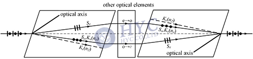
Note that the separation of o-ray and e-ray in Fig.8 is not symmetric. Thus the input and output optical beams in Fig.9 are not collinear, which is not preferred by designers of optical devices. The BD block can be revised as Fig.10. O-ray and e-ray are separated symmetrically in the crystal by inclination of the incident and outgoing interfaces. The inclination angle γ and orientation χ of the optical axis need elaborate design. The angle between e-wave normal Ke and optical axis is kept as Eq. (8) and thus the maximum deviation angle between e-ray and o-ray is kept as Eq. (9). Based on paraxial approximation, the inclination angle of the incident and outgoing surfaces is obtained as Eq. (10), where n2 is obtained according to Eq. (2) given θ=θc as Eq. (8).

(10)

With the optimized BD crystals, the optical devices in Fig.9 is revised as Fig.11. The input and output optical beams are collinear now, which facilitates the coaxial assembly of the optical device.

Wollaston Prism
Wollaston prism is another optical element separating two orthogonally polarized beams. The difference between BD crystal and Wollaston prism is that the former separates two beams by a lateral distance, while the latter separates two beams by an angle. As shown in Fig.12, a Wollaston prism comprises two wedges made of uniaxial crystal. The optical axes of the wedges are both parallel to the right angle surfaces, while the two optical axes are perpendicular to each other when the wedges are assembled together. Thus in the first and second wedges, the p-wave acts first as e-ray and then as o-ray, while the s-wave acts as first o-ray and then e-ray.

Natural light incidents on the first wedge normally. O-ray and e-ray keeps coincidence in the first wedge but transmit in different speed (c/no and c/ne, given c as the optical velocity in vacuum). When the two rays are refracted at the angular surface between two wedges, the refraction angles are different. One is larger than the incident angle φ and the ray turns downward. The other is smaller than φ and the ray turns upward. The angular deviation between the two rays is enlarged after refraction at the right angular surface of the second wedge. Based on paraxial approximation, the final deviation angle between the separated s-wave and p-wave is given by Eq. (11).

(11)
Wollaston prism is widely used in optical devices such as optical isolator, polarization beam combiner/splitter, optical circulator, and wavelength selective switch, etc.
Written by Zhujun Wan, HYC Co., Ltd
